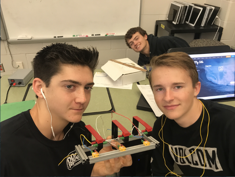
For this project, we had to design a circuit that was able mimic a copier when it jams up. There are three photo sensors that are paired with three lamps. If an object breaks two adjacent light beams at the same time, a logic 1 is outputted. When two adjacent beams are not broken at the same time, a logic 0 is outputted. If everything works good, paper will pass through without breaking two beams at once. In the case of two beams being broken at once, an alarm will sound.
We had a couple of constraints for this project. We had a time constraint, material constraint and we had to work in partners.
We had a couple of constraints for this project. We had a time constraint, material constraint and we had to work in partners.
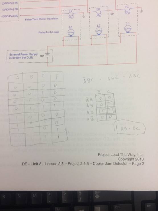
The big table to the left is the truth table. The expression at the top is the un simplified expression. Below it is the k mapping where i was able to get the simplified expression of AB + BC.
- The resistors are used to limit the amount of power flowing through the circuit
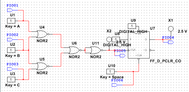
- The computational logic circuits purpose is to set off the alarm when two adjacent beams are broken at the same time. Meaning there is a paper jam.
- We used flip flops because we needed the buzzer to continue buzzing until the reset signal was activated.
- The LED and buzzer are both activated when there is a jam but the LED turns off automatically when the buzzer stays on. This is because the buzzer needs to stay on until the problem is fixed and then the buzzer can be turned off. The LED turns off as soon as the jam is no longer present.
Conclusion:This project is different in the fact that we utilized AOI logic gates plus sensors instead of switches, buttons and clocks. In this project i learned, we can use AOI logic gates as inputs as well as sensors and how to use other devices than switches for inputs in a circuit.
