|
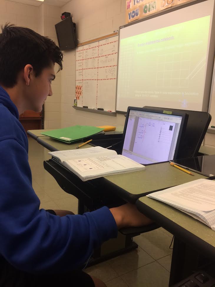
This was the date of birth project. In this project, we had create a circuit that would display out birth dates using a seven segment display. This project had a couple of constraints which included, using 2 input gates, using at least one NAND or NOR gate and completing it within the time constraint.
|
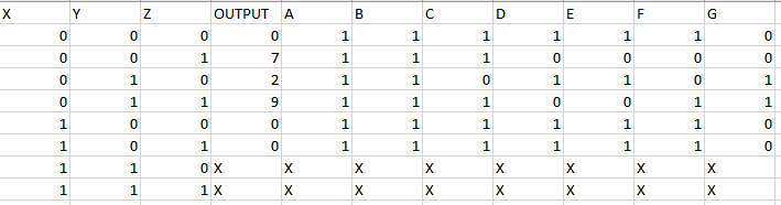
Truth Table:
This is the truth table that is specified to my birth date. There are three inputs with X, Y and Z and eight different output rows, for each leg of the seven segment hexadecimal display with A, B, C, D, E, F and G. The other output row is the row that gives the numbers for my birth date. All the other output rows are the signals that will make those numbers on the seven segment display. There are eight rows because of the relationship of 2^of the number of inputs. The rows of the inputs are in order of increasing binary numbers. This table shows all the signals that are needed to show 07/29/00
This is the truth table that is specified to my birth date. There are three inputs with X, Y and Z and eight different output rows, for each leg of the seven segment hexadecimal display with A, B, C, D, E, F and G. The other output row is the row that gives the numbers for my birth date. All the other output rows are the signals that will make those numbers on the seven segment display. There are eight rows because of the relationship of 2^of the number of inputs. The rows of the inputs are in order of increasing binary numbers. This table shows all the signals that are needed to show 07/29/00
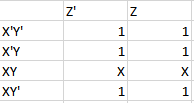
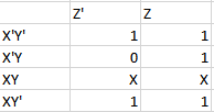
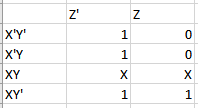
K-Mapping:
These are all of the K-Maps for all of the different legs of the seven segment display. K-Mapping is pretty much a short cut to finding out the logic expression for all the different outputs. For an eight row truth table, the K-Map will have two columns and four rows. For X,Y and Z inputs, the table is labeled on the left with X'Y' on the top row and going down is X'Y, XY and on the bottom row is XY' ( The ' means that that input is inverted). On the top, the left column is labeled with Z' and the right column is labeled with Z. To fill out the spaces, you go from top to bottom of the signals for that output. Filling out the K-Map with those values from left to right going straight down. Then you switch the last two rows of the truth table. Once all the K-Maps are filled out for all of the outputs, its time to start grouping to find your simplest logic expression. Only ones are grouped together in the K-Maps ( and X's because they can act as a zero or a one.) You can group the ones or X's in groups of ones, twos, fours or eights. Including "Pacmaning" from top to bottom or side to side. Your goal is have the least amount of groups that you can have. Once you have all of the groups, you look at the labels and see what cancels to arrive at your final logic expression which in this case are all in Sum of Product form. We used K-Mapping because it is a much simpler and faster way to find the simplest logic expression.
These are all of the K-Maps for all of the different legs of the seven segment display. K-Mapping is pretty much a short cut to finding out the logic expression for all the different outputs. For an eight row truth table, the K-Map will have two columns and four rows. For X,Y and Z inputs, the table is labeled on the left with X'Y' on the top row and going down is X'Y, XY and on the bottom row is XY' ( The ' means that that input is inverted). On the top, the left column is labeled with Z' and the right column is labeled with Z. To fill out the spaces, you go from top to bottom of the signals for that output. Filling out the K-Map with those values from left to right going straight down. Then you switch the last two rows of the truth table. Once all the K-Maps are filled out for all of the outputs, its time to start grouping to find your simplest logic expression. Only ones are grouped together in the K-Maps ( and X's because they can act as a zero or a one.) You can group the ones or X's in groups of ones, twos, fours or eights. Including "Pacmaning" from top to bottom or side to side. Your goal is have the least amount of groups that you can have. Once you have all of the groups, you look at the labels and see what cancels to arrive at your final logic expression which in this case are all in Sum of Product form. We used K-Mapping because it is a much simpler and faster way to find the simplest logic expression.
|
A K-Map
Logic Expression = 1
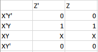
C K-Map
Logic Expression = Y' + Z
E K-Map
Logic Expression = X + Z'
|
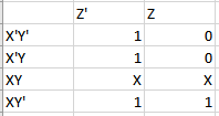
B K-Map

Logic Expression = 1
D K-Map
Logic Expression = X + Z'
F K-Map
Logic Expression = X + Y'Z' + YZ
|
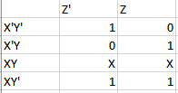
G K-Map
Logic Expression = Y
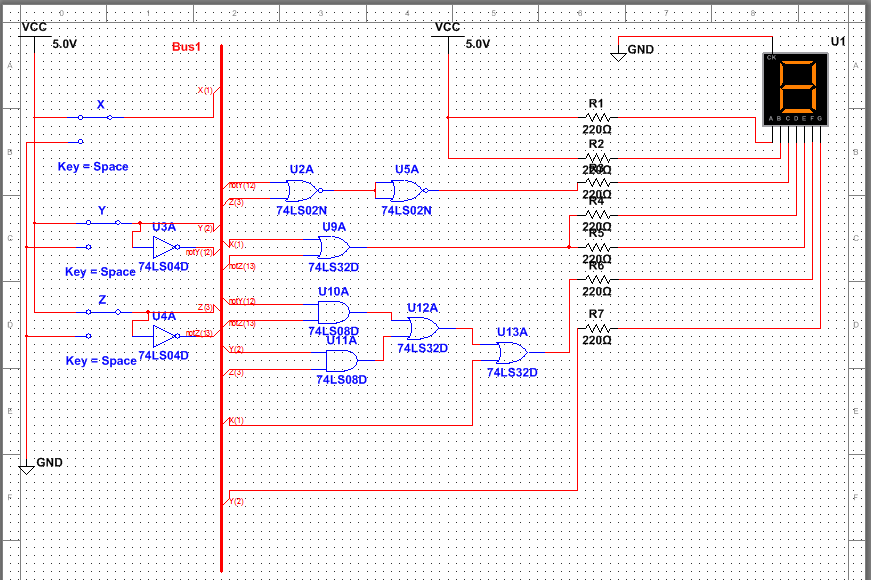
MultiSim Circuit
This is the working circuit that correctly displays the numbers of my birth date through a seven segment display. This circuit is in Bus form to save time and space while building it. There are three inputs with X, Y and Z which are all connected to power and are all grounded. Only inputs Y and Z require inverters because there are no inverted X's in the logic expressions. There were seven different individual circuits that i needed to build for each leg of the display. We used a common cathode seven segment hexadecimal display which had to be grounded. Only nine different gates were needed to build this circuit which meant that only four chips were needed when actually bread boarding the circuit. We had to build at least one of the individual circuits using either NAND or NOR gates. We use NAND or NOR sometimes instead of AOI because in some cases, it can save the number of chips that would be required to build the actual circuit. Using NOR for one of my circuits required one more gate than it would have if i had just used AOI. This dosent change the number of chips that would have had to of been used. But if less chips were required, then that would decrease the cost when building the actual circuit. Like i said earlier, we used a common cathode seven segment hexadecimal display which is a display which always needs to be grounded. If we used common anode, then the display would always need to be connected to power. We used the common cathode because its easier to think of a one as being on and a zero as being off. The resistors placed before the seven segment display are there so that they can control the amount of current that flows into the seven segment display.
This is the working circuit that correctly displays the numbers of my birth date through a seven segment display. This circuit is in Bus form to save time and space while building it. There are three inputs with X, Y and Z which are all connected to power and are all grounded. Only inputs Y and Z require inverters because there are no inverted X's in the logic expressions. There were seven different individual circuits that i needed to build for each leg of the display. We used a common cathode seven segment hexadecimal display which had to be grounded. Only nine different gates were needed to build this circuit which meant that only four chips were needed when actually bread boarding the circuit. We had to build at least one of the individual circuits using either NAND or NOR gates. We use NAND or NOR sometimes instead of AOI because in some cases, it can save the number of chips that would be required to build the actual circuit. Using NOR for one of my circuits required one more gate than it would have if i had just used AOI. This dosent change the number of chips that would have had to of been used. But if less chips were required, then that would decrease the cost when building the actual circuit. Like i said earlier, we used a common cathode seven segment hexadecimal display which is a display which always needs to be grounded. If we used common anode, then the display would always need to be connected to power. We used the common cathode because its easier to think of a one as being on and a zero as being off. The resistors placed before the seven segment display are there so that they can control the amount of current that flows into the seven segment display.
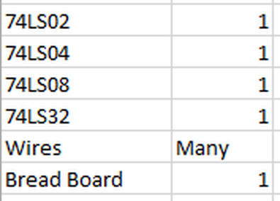
Bill Of Materials
This is a table to shows what materials i used and the amount of each.
This is a table to shows what materials i used and the amount of each.
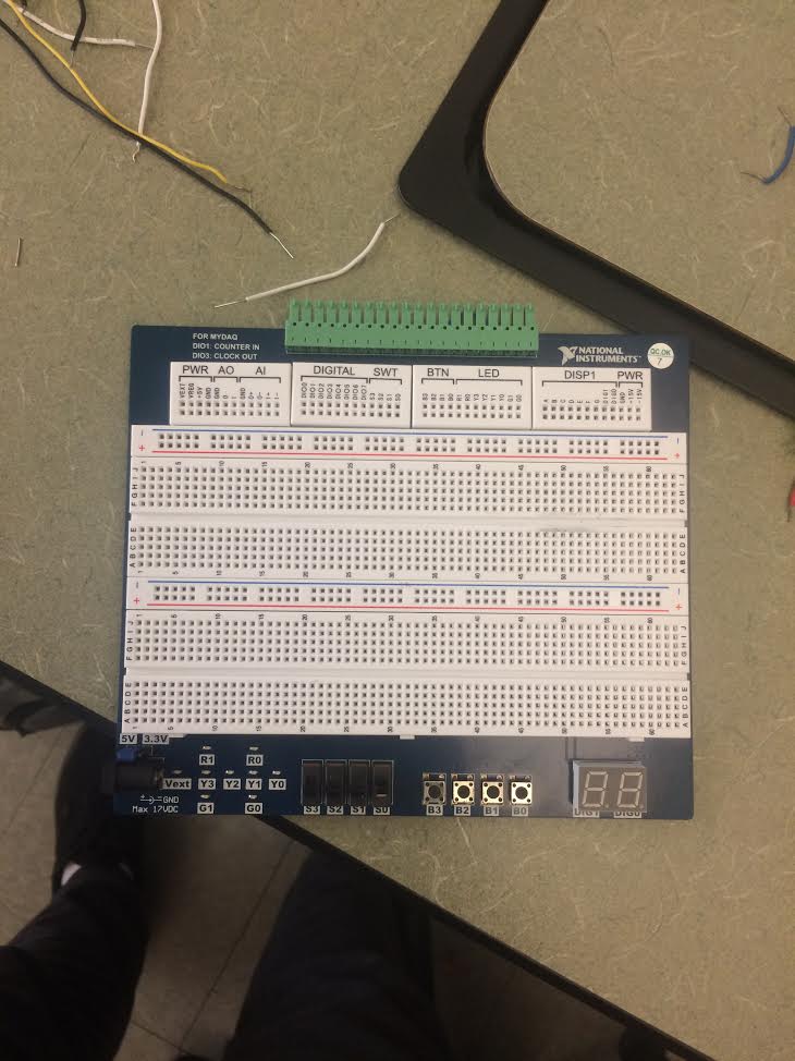
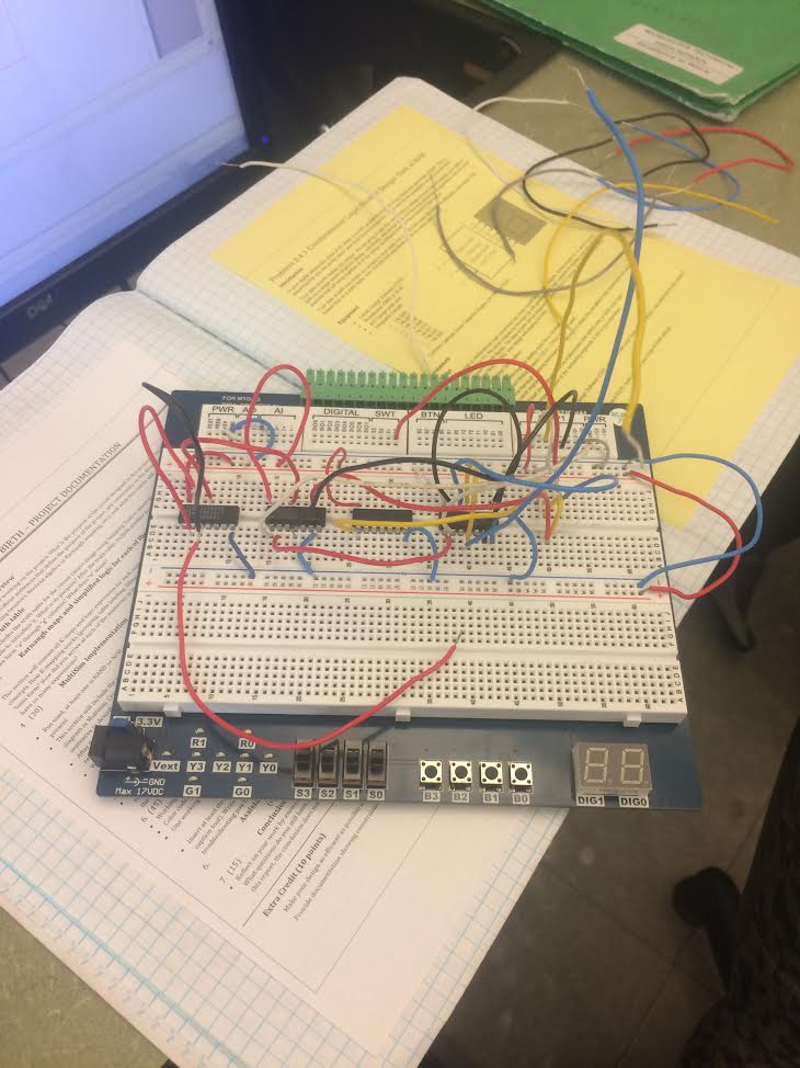
Bread Boarding:
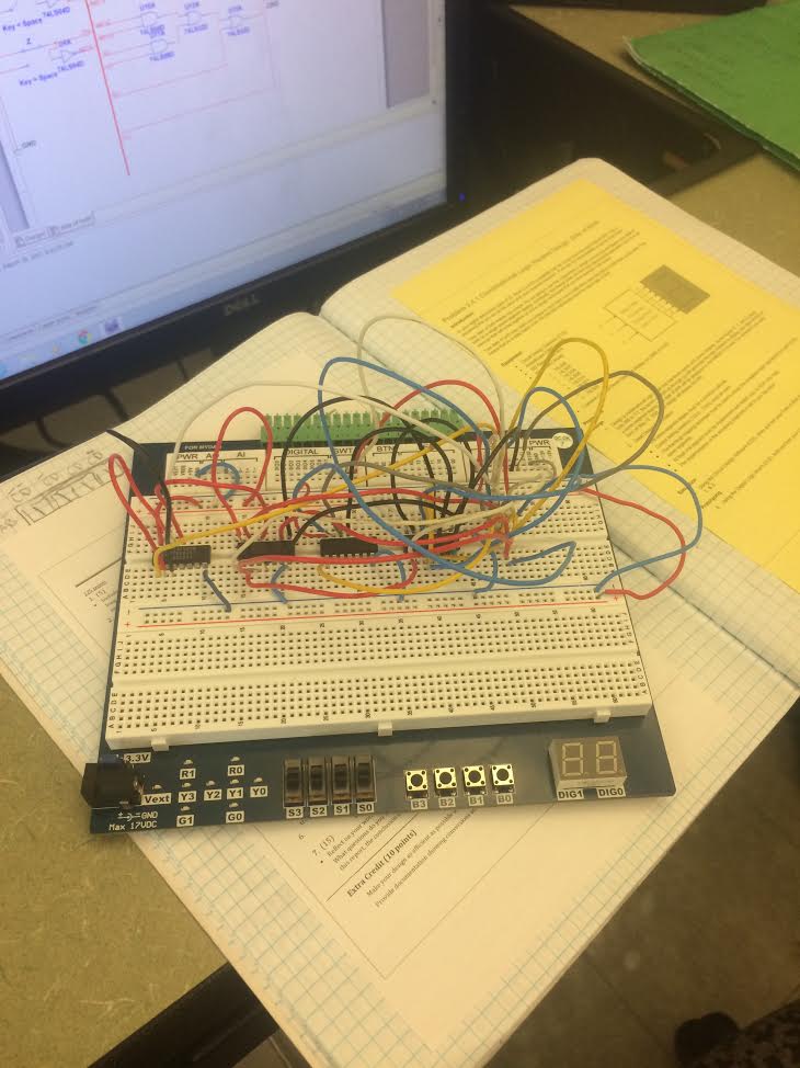
Here is a before, during and after picture of the breadboard that i built based on the circuit that i came up with. This bread boarding experience was my second time bread boarding and i think it was a much better experience. I was able to build the circuit mostly by myself, without the hep of my peers. I got six out of the seven legs to the display to work which showed most of the number that i wanted but not he whole number. I used trouble shooting to try and find the problem with that one leg but we could not figure out what the problem was. In the end, i did learn a lot about bread boarding and how to build circuits.
Here is a before, during and after picture of the breadboard that i built based on the circuit that i came up with. This bread boarding experience was my second time bread boarding and i think it was a much better experience. I was able to build the circuit mostly by myself, without the hep of my peers. I got six out of the seven legs to the display to work which showed most of the number that i wanted but not he whole number. I used trouble shooting to try and find the problem with that one leg but we could not figure out what the problem was. In the end, i did learn a lot about bread boarding and how to build circuits.
|
|
Conclusion:
I learned form this project that circuits can really be used for pretty much anything you want to represent. Birthdays would be a prime example of that. If i were to do this project gain, i would give myself more time to bread board so that i would have more time to not make any mistakes. One question i do still have after this project is how to figure out the number of chips needed based on the number of gates that you have in your circuit. This project would have been way more difficult if it weren't for K-Mapping because that just made finding the logic expressions so much easier and faster.
I learned form this project that circuits can really be used for pretty much anything you want to represent. Birthdays would be a prime example of that. If i were to do this project gain, i would give myself more time to bread board so that i would have more time to not make any mistakes. One question i do still have after this project is how to figure out the number of chips needed based on the number of gates that you have in your circuit. This project would have been way more difficult if it weren't for K-Mapping because that just made finding the logic expressions so much easier and faster.
