For this project, we had to build a circuit that was able to count from 0 to 80 with a reset switch. The circuit had to count to 80, pause and reset when the switch was pushed.

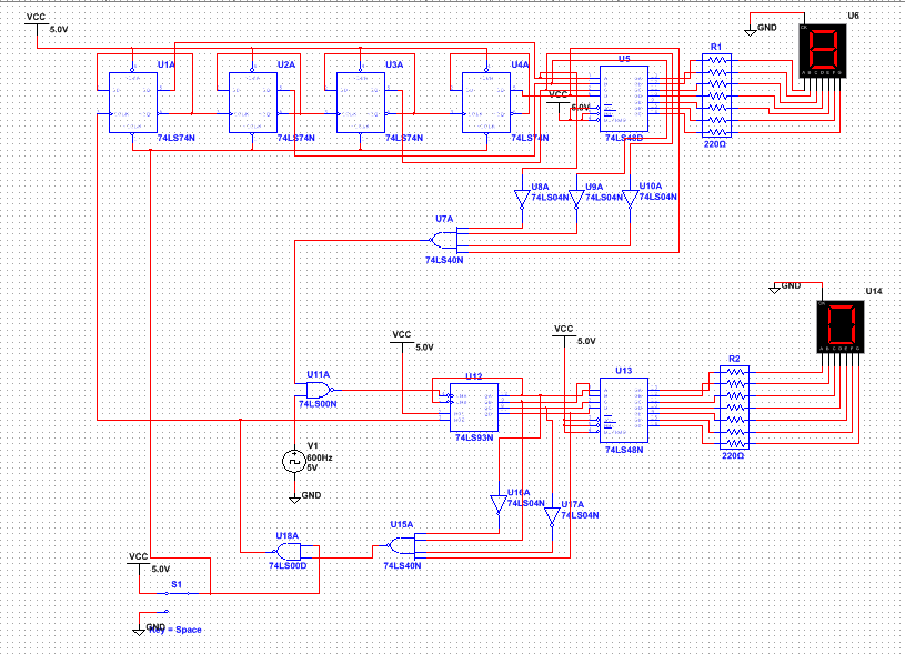
MultiSim Cicuit
PLD Circuit
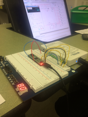
The PLD mode is used when we need to upload our circuits to breadboards. It is different from design mode because the design mode is where you can build your circuit to test it with hex displays. In PLD mode, there are input and output pins that we can assign so that we are able to wire the circuit once we upload it. I assigned input pins for the clock and reset switch and output pins to the 7 segment display legs. To transfer the circuit, you transfer and export to PLD. Then set the required settings and wait until the transfer is done.
Bill of Materials:
CMOD: 1
Breadboard: 1
Companion: 1
Wires: A lot
CMOD: 1
Breadboard: 1
Companion: 1
Wires: A lot
Connection: MSI circuits have more gates per IC than SSI, so MSI is easier to work with with more complicated circuit. MSI circuits can only count up and they have to start at zero. The ripple effect is the effect when consecutive flip flops are set up and the flip flops rely on the previous one to work. Except for the first one, which relies on the clock. The circuit is set up with a tens counter and a ones counter that are both asynchronous, meaning they rely on the previous counters to move forward. The reset switch is pushed to begin the counting at zero. This causes a trigger in the 93 chip which begins the ones counter to count up to 9 and once it hits 0, the tens counter displays a one. Then the circuit stops counting when the tens hits an 8 and the ones hits a 0. Then the reset switch resets the circuit counter back to both zeros. So, there is one counter going from 0-9 and another going from 0-8 which rely on each other.
