|
DEFINE THE PROBLEM
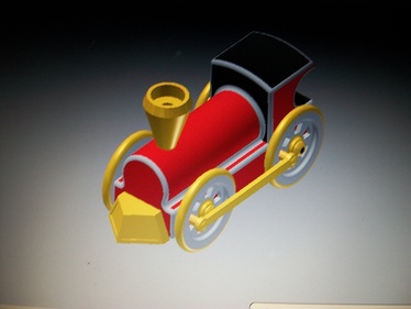
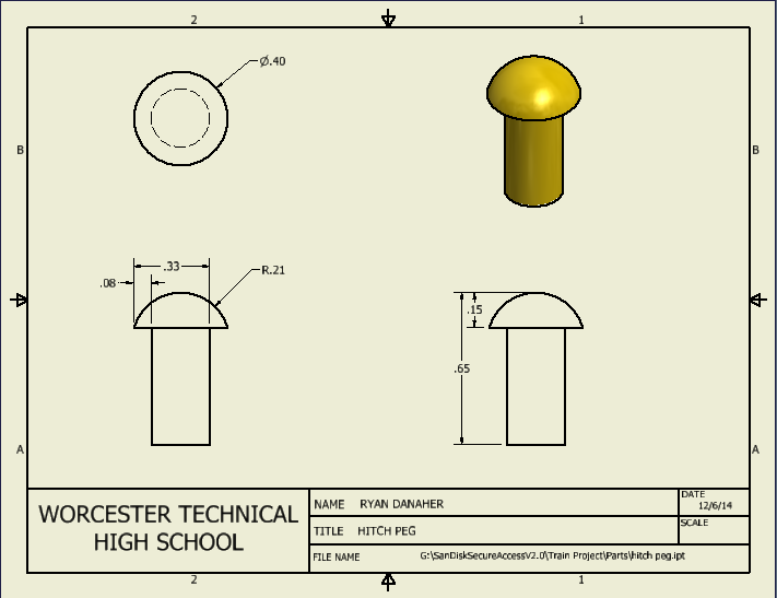
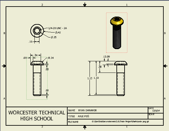
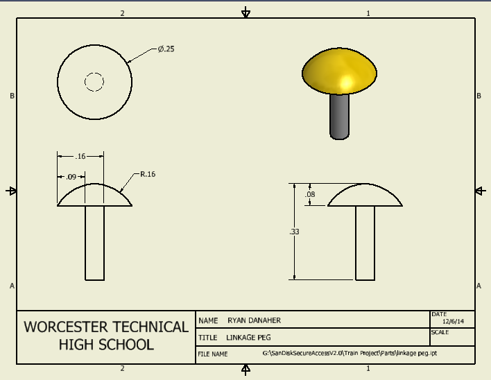
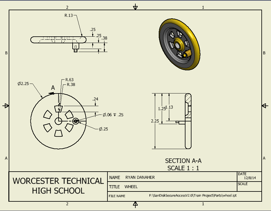
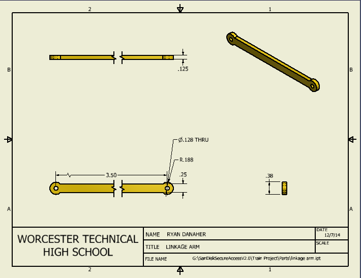
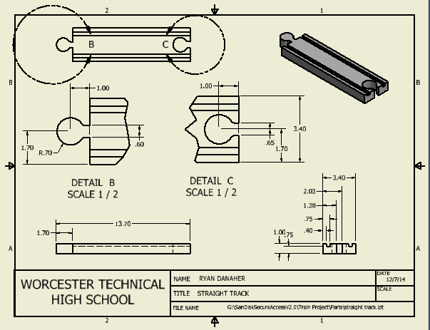
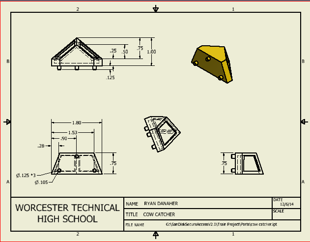
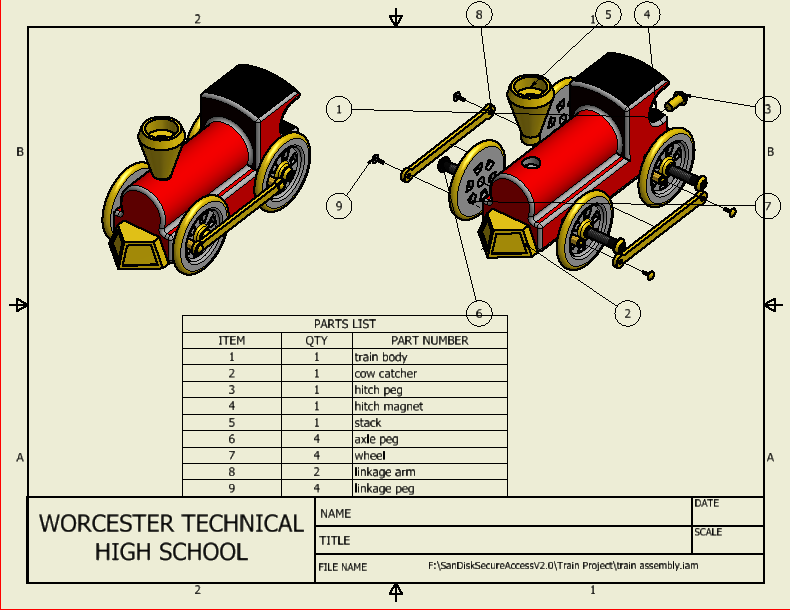
In this project we were suppose to design and model a miniature train on Autodesk inventor. We had to model and dimension each individual part then assemble all of them together to create the whole train. Then after we were done assembling, we had to create multi view drawings of each part with dimensions and tolerances. |
GENERATING CONCEPTS
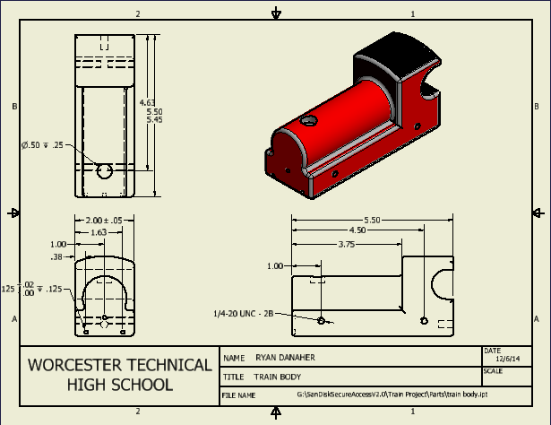
I got started modeling with the main train body first. Some of the dimensions were a little hard to figure out, but after a little bit of time, I got them. All of the modeling took a lot of different skills on inventor and were somewhat challenging. Reading most of the dimensions were pretty straight forward but some required you to use a little math to figure out. |
|
|
|
|
|
|
|
|
|
|
EVALUATE THE SOLUTION
When I asked my friends for some advice they gave me one piece of advice. I was told that the video of the animated train would look better if it were not pixilated and were smaller. Other than that, my webpage and overall project looked good.
When I asked my friends for some advice they gave me one piece of advice. I was told that the video of the animated train would look better if it were not pixilated and were smaller. Other than that, my webpage and overall project looked good.
REFLECTION
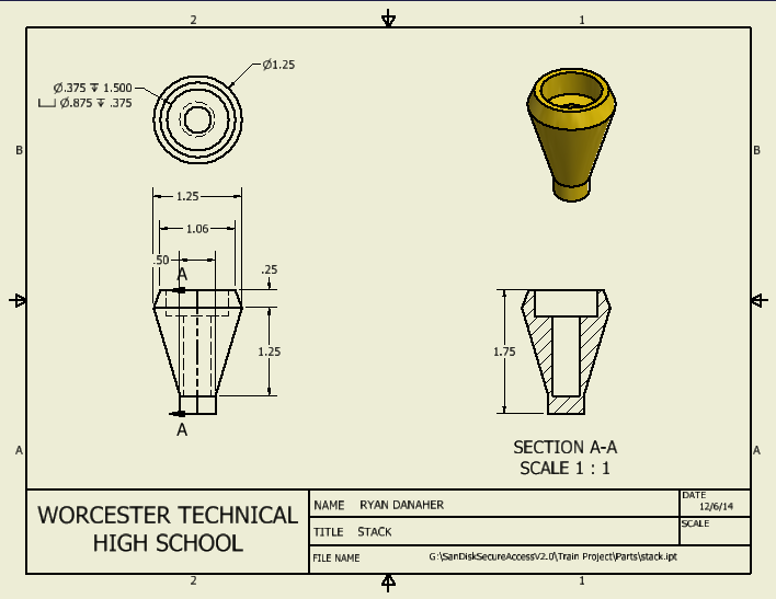
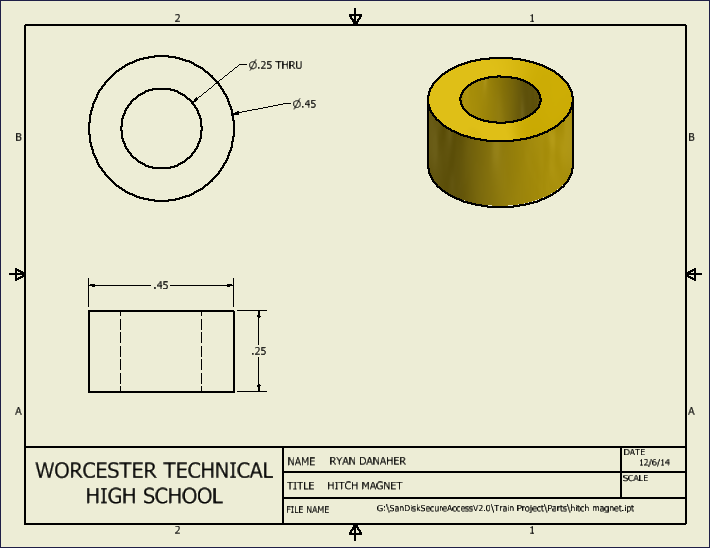
There were several challenges that I faced during this project. One challenge that I faced while doing this project was using all of the different skills that were required on Autodesk inventor. There were several different skills that I had to use on all of the different pieces of the train when I was modeling them on inventor. For example, I had to use features such as fillet, loft, chamfer, shell, hole (different types of holes), revolve and thread. Also figuring out all of the different dimensions was sort of tricky. Then the other major challenge was creating and dimensioning all of the multi view pages for all of the different parts. I had to list the specific dimensions that were required and give whatever tolerances that were supposes to be on that part. That was tough getting all of those together and making sure that they were correct. The purpose of a sectional view is to show the interior features of an object or irregular shape (it cuts away a certain percentage of an object). The purpose of an auxiliary view is to show the true dimensions of a slanted face. The purpose of a broken view is to show an object in several different broken up pieces. The reason that you use symbols instead of words to describe holes is to avoid clutter when dimensioning. Finally, tolerances are needed because they allow room for variation without interrupting an objects ability to function correctly.
There were several challenges that I faced during this project. One challenge that I faced while doing this project was using all of the different skills that were required on Autodesk inventor. There were several different skills that I had to use on all of the different pieces of the train when I was modeling them on inventor. For example, I had to use features such as fillet, loft, chamfer, shell, hole (different types of holes), revolve and thread. Also figuring out all of the different dimensions was sort of tricky. Then the other major challenge was creating and dimensioning all of the multi view pages for all of the different parts. I had to list the specific dimensions that were required and give whatever tolerances that were supposes to be on that part. That was tough getting all of those together and making sure that they were correct. The purpose of a sectional view is to show the interior features of an object or irregular shape (it cuts away a certain percentage of an object). The purpose of an auxiliary view is to show the true dimensions of a slanted face. The purpose of a broken view is to show an object in several different broken up pieces. The reason that you use symbols instead of words to describe holes is to avoid clutter when dimensioning. Finally, tolerances are needed because they allow room for variation without interrupting an objects ability to function correctly.
