This circuit was designed to simulate a majority vote voting machine that met the specific design principles. We were given scenarios of how either the president, vice president, secretary or treasurer would vote and what the outcome would be. We were told that the decision would be a pass if the majority voted but, in case of a tie the presidents vote would be the outcome. We could also only use two input gates only throughout the circuit.

|
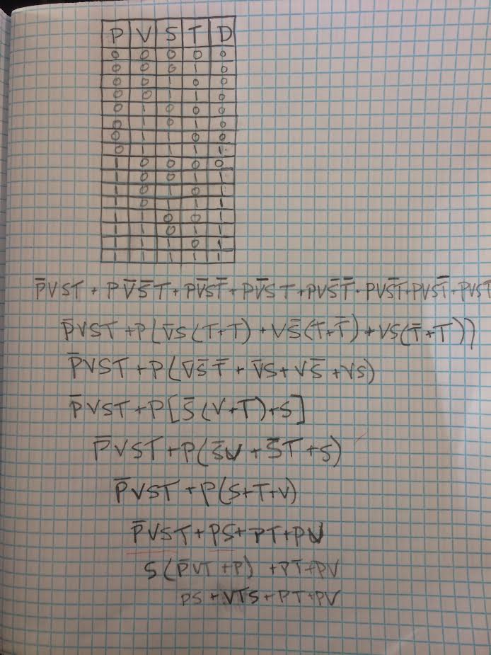
This is the truth table that shows what outcomes will be produced due to different scenarios. There are 16 different rows because of the 4 different inputs. Each variable stands for a certain person. P = President, V = Vice President, S = Secretary and T = Treasurer. The D column stands for a decision to if the law will be passed or rejected, a 1 in this column means a pass and a 0 means a reject. The 1's and 0's in the other columns stand for if they voted a yes or no ( 1's being yes and 0's being no). Whatever the majority vote was, was going to be what the decision was. But in the case of a tie, whatever the president voted would be the decision.
|
|
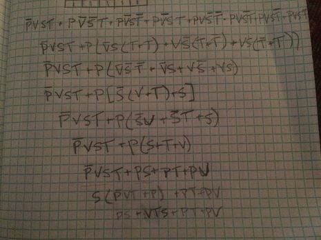
The equation directly under the table to the left is the unsimplified expression for table in the Sum Of Products form. A variable with a dash above it means the vote was a no and no dash means a yes. This is an equation that gives every scenario to when the decision would be a pass. There are eight minterms for the eight different scenarios that would result in a pass ( a 1 in the D column). I chose to create a SOP form because it makes it very easy to see all the different minterms and what scenarios give an outcome of a pass.
|
|
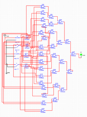
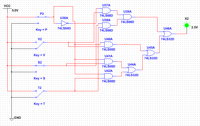
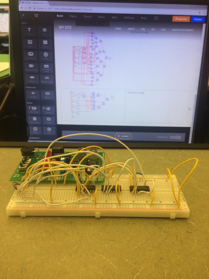
This is the unsimplified circuit. The circuit is composed of one 5 volt power source and a ground. Connected to those two are four different inputs, P,V,S,T. All of these inputs are connected to NOT gates so that they can be regular or inverted. From there, 24 AND gates were needed to multiple all the different components together. After that, 6 OR gates were needed to add the final products to create the final output. This circuit required a total of 34 gates which shows how tedious it was to build the unsimplified circuit and how useful boolean algebra is to simplify circuits such as this one. This is the boolean algebra that was required to simplify the expression. This made it a lot easier to build a simpler circuit and for the final breadboard we had to assemble. The simplified circuit is a lot simpler, easier to follow and neater than the unsimplified version. The circuit required significantly less gates and wiring. The purpose of the resistor before the LED is to join all of the minterms together. I used a total of 6 AND gates, 3 OR gates ans no inverters. Along with 2 74LS08 chips and 1 74LS04 chip.
The simplified circuit required less gates and circuits. It required four less inverters and 21 less total gates. This is a save on money, time and chance for human error. When building the circuit, more materials means higher cost and more time needed for construction. The more complicated a circuit is also means the higher chance to make a mistake. |
Bill Of Materials
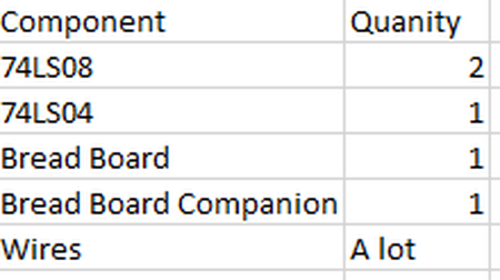
This table shows the materials used to construct the circuit and the quantity of how many were needed.
|
|
|
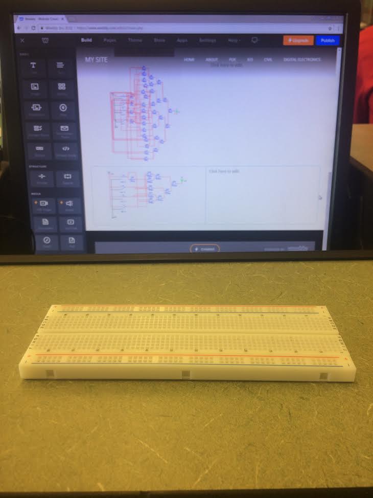
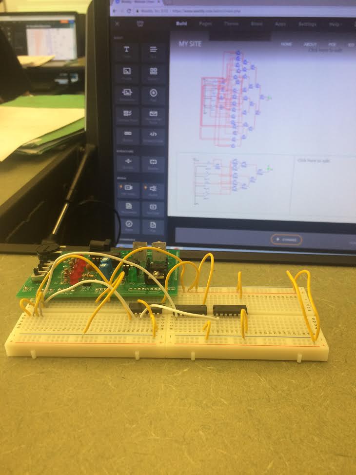
The picture all the way to the left is the blank bread board before i started to build the circuit. The middle picture shows the circuit when i was about half way done. The picture to the right is the final fully functioning circuit.
My first bread boarding experience came in Digital Electronics when Mrs.Z went over step by step, and very slowly, how to build a very simple circuit. I had no idea what i was doing with a bread board then and now i have a good handle on how to build a functioning circuit on a bread board. Mistakes i would make would be putting wires in wrong rows, not connecting the right wire to either positive or negative, not bridging the correct things, etc. Troubleshooting has helped me tremendously in becoming efficient at this. Comparing and contrasting with others in the class to see what is wrong with mine forced me to learn what mistakes i made and how to fix them.
Conclusion:
This project, though it was long and tedious, was a project that i took a lot away from. From reading and understanding a problem given, to creating truth tables and expressions, to using MultiSims and finally to bread boarding which i learned a lot about. Reading and understanding a problem came at the beginning when we had to read the Majority Vote problem that was given and understand what was being described. From there i was able to create a truth table from what i understood from the problem. Once i finished the table, i was able to create an expression in SOP form and eventually simplify it with boolean algebra. This step showed me how important boolean algebra is to this process. Using that algebra, we are able to simplify very complicated circuits to smaller and easier circuits to work with. After i found both the unsimplified and simplified expressions, I moved onto MultiSims where i built both of the circuits on the computers. Once i had both of the circuits built on the computer, I was able to begin assembling the bread board circuit. So in conclusion, finishing a circuit design takes a lot more steps than you would normally think and a lot goes into constructing one simple circuit.
This project, though it was long and tedious, was a project that i took a lot away from. From reading and understanding a problem given, to creating truth tables and expressions, to using MultiSims and finally to bread boarding which i learned a lot about. Reading and understanding a problem came at the beginning when we had to read the Majority Vote problem that was given and understand what was being described. From there i was able to create a truth table from what i understood from the problem. Once i finished the table, i was able to create an expression in SOP form and eventually simplify it with boolean algebra. This step showed me how important boolean algebra is to this process. Using that algebra, we are able to simplify very complicated circuits to smaller and easier circuits to work with. After i found both the unsimplified and simplified expressions, I moved onto MultiSims where i built both of the circuits on the computers. Once i had both of the circuits built on the computer, I was able to begin assembling the bread board circuit. So in conclusion, finishing a circuit design takes a lot more steps than you would normally think and a lot goes into constructing one simple circuit.
